Home »
OVERVIEW
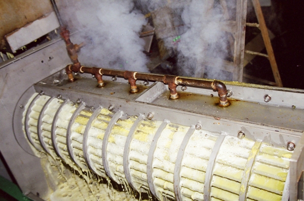
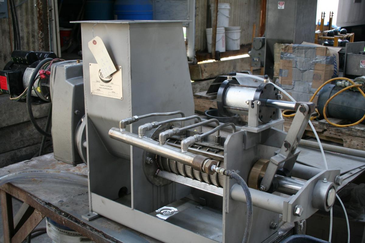
The Vincent TSP press consists of a pair of overlapping screws rotating within a screen housing, a flanged inlet hopper, and a discharge opening. At the discharge end, the mouth of the screen housing is closed by a pneumatically actuated dual cone assembly which moves back and forth on the screw shafts in proportion to the internal pressure in the screen frame. This motion is opposed by the thrust of the cone cylinders, thereby regulating the discharge of solids. An air regulator is provided to adjust the pressure on the cone assembly. The liquids, which are squeezed from the wet product, escape through the screen housing and are caught in a built-in pan under the screen.
The screw is driven by a fixed speed electric motor that is mounted to a gearbox. The gearbox reduces the RPM from the typical 1750 or 1175 RPM output of the motor to an appropriate speed for the application, 9 – 50 RPM. The gearbox mounts to the frame of the press and is coupled to one or both screws.
The numbers in the model designation stand for the nominal diameter of the screws in inches.
As the press has been adapted to many different applications, options have been added to the press. These include interrupted or continuous flighted screws, conical screws where the shaft increases in diameter, different shape inlet hoppers, different style cones, etc. As a result, not all the information contained in this manual will apply to your press.
RIGGING
Be sure to properly support the press when lifting it from the truck. Do not lift just one corner and drag, as it is possible for the frame to deflect, which in turn can shift the screws’ positioning within the press. Interference between the screws and the screens can result.
INSTALLATION
Be careful to not to rack the press when tightening the mounting bolts. In the case of large presses, do not just bolt or weld the press down to a level foundation! Instead, first place the press where it is to be installed. Next, place shims between the press frame and the steelwork (or floor, concrete pedestal or foundation) to fill any gap where the press is to be anchored. Only after shimming (or grouting) should the press be pulled down tight. Doing otherwise can rack the frame of the press, and this can cause screw-to-screen interference.
A large press must be mounted solidly, preferably to a foundation or structural steel. If a press draws its full rated horsepower without the press being anchored to the floor, the frame of the press can twist.
For maintenance, the screws are removed through the cake discharge end of the press. At installation, allow the space required for such maintenance.
Material can be fed into the press many ways. You may need to allow for return of overflow material in the event that more is fed to the press than it can take. A level sensor for the inlet hopper can be useful for controlling the feed rate going into the press.
Spill containment is a consideration which should be taken into account, because it may be possible for un-pressed material to purge from the cake discharge of a press.
We recommend that a manual disconnect, for killing power to the motor, be installed close to the press.
When material is piped to a press in a closed piping system, it is important to have a 2″ vent line open to the atmosphere, along with an overflow return line. The vent is necessary to prevent a siphon effect which can induce a vacuum in the inlet hopper and reduce press capacity. The return line should empty above the surface of the return pit. The overflow should fill less than half of the cross section of the return line.
It order to provide space for a cake take-away conveyor, the press can be installed tilted with an elevated discharge. Consult the factory, as the oil level in the gearbox may have to be adjusted.
INVERTER VFD & PLC CONTROL
An inverter VFD (variable frequency drive) must be used to start, protect, and operate a twin screw press. With a VFD it is possible to establish the optimal combination of speed and discharge cone air pressure. The VFD also can be used to reverse the press in case of a jam or to slow it down during upset conditions.
Nine presses out of ten will operate unattended, indefinitely, and just fine at line frequency of 50 or 60 Hertz. If two screw presses are mounted in parallel, they are usually fed with a screw conveyor which drops to fill the first press, with the rest going to the second press; this is followed with a drop-out for overflow.
However, we need to address the exceptions:
Use of level controls is becoming more and more common. These are used to regulate either the flow going into the press or to regulate the screw speed.
In some applications a press is sized for handling upset conditions of large flow, while the normal flow is quite small. In these cases a level control is used, and the PLC can be programmed to turn off the press when a low level is reached in the inlet hopper, and the press re-started when a higher level is signaled.
In some cases the press will tend to jam, overload, and trip out on high amps. In this situation it may be necessary to program the controls so that the cone automatically goes open on high amps, re-closing at a lower set point. This arrangement requires a solenoid operated 4-way air valve, replacing the manual cone positioning valve which is provided with the press.
In other cases of jamming, a simpler arrangement is to install a Cone Timer. A timer is used to periodically open the cone. The closed period is determined by the amount of time required for press cake to accumulate in the press. The duration of the “cone open” period is long enough to dump most of the press cake that has formed. This type of operation may be used if the press periodically experiences jamming or overload due to fluctuations in the amount of material being fed into the press. Alternatively, it may be used with slippery or slimy press cake that cannot be dewatered to sufficient firmness to force the cone open. Cone Timer panels are available from Vincent at a minimal cost.
In some installations a solenoid operated air valve is used to open the cone whenever high motor amps are detected. A simple Red Lion control is available for this.
Some applications require the use of a specially programmed VFD. In this case the VFD is not used to change the speed of the press, but, rather to set it for auto-reversing operation. By having the screw run backwards for three or four turns every few minutes, some difficult-to-dewater materials can be pressed much more effectively. This operation can help a great deal with material which tends to blind (cover over) the openings in the screen. Vincent has loaner VFDs if you want to give it a try. The technique works well on wedgewire screens; care must be taken with perf screens so that the screw does not snag the screen during the reverse cycle.
Once through start-up, the cone is almost always permanently left in the closed position at whatever air pressure has been found to be effective. A plug of cake will be left around the cone whenever the press is turned off; this will clear on its own accord on restarting the press.
However, some materials may set up and become hard or freeze within the press when the press in turned off. This is especially true in the case of pressing wet coffee grounds or outdoor installations. For these applications it is advisable to open the cone for a period of two minutes before turning off the press. This allows the press to partially empty itself, fluffing the material left in the press. Vincent can provide information for automating this procedure.
INSTRUMENTATION
Twin Screw Presses are very sensitive to changes in screw speed. This is one reason a VFD should be used with the drive motor. A more important reason for using a VFD is that it affords instantaneous protection in case of a surge in motor load. Such a surge could indicate that tramp material has entered the press or that the overlapping screw flights are interfering with each other.
The VFD should be set to read motor load or amperage. The most useful information to have when testing a press is amp draw. The load drawn by the drive motor of the press is indicative of how much work the press is doing. The higher the amps, the better the dewatering. Also, the higher the amps, the closer the press is to jamming, and the greater is the abrasive wear. Very low amps indicate little dewatering is being done; the screen is blinded; low compression is taking place; or the flow into the press has stopped.
A moisture balance is valuable for measuring the moisture content of the inbound material and of the press cake. If an oven is used to dry samples, be sure it is set at 160o F or less if there are sugars in the sample. Samples should be left in the oven overnight. The tare weight of the pan should be much less than the weight of the sample which is being dried.
As mentioned previously, level controls can be useful in operating a press. With a signal providing the depth of material in the inlet hopper, the speed of the press can be varied to match the flow going into the press. With egg shells, a simpler level control is used to only signal when a high level is reached; its signal will increase the screw speed. In special cases the press can be turned off when a low level is reached and re-started when a higher level is reached.
In the case of pressing liquids that contain dissolved sugars or salts, a refractometer is valuable for assessing press performance. The Brix of the inbound flow, the press cake, and the press liquor will all be the same figure. The higher the Brix, the higher will be the solids content of the press liquor.
If dissolved (soluble) solids are present, the suspended (insoluble) solids (fiber) in the press liquor are generally measured by filtering and washing a sample and drying the filter paper in an oven. Dissolved solids will be washed from the sample during the washing process.
IMPORTANCE OF SYNCHRONOUS TWIN SCREW DRIVE
Synchronous turning of the two screws of a Twin Screw Press is of paramount importance. Should one screw get out of step with the other, severe damage can result to both the screws and screens.
In some Twin Screw Presses, the screws are kept synchronized by a pair of spur gears, one driving the other. If tooth wear occurs, it can lead to tooth breakage. This would allow one screw to run into the other. For this reason the spur gears should be inspected frequently for any sign of wear.
If for any reason screws are to be removed from a Twin Screw Press, care should be taken so that proper synchronization is established upon re-assembly. Vincent can assist with this.
MOTION DETECTOR
Most twin screw presses come with speed indicators mounted on the outboard ends of both screws. These are part of an important safety interlock. Their signals are fed to a control box which sends a signal to the VFD to shut down the press should any difference be noted between the speeds of the two screws.
The screw shaft flights overlap in the Twin Screw Presses, and the flights on one shaft are 90 degrees offset from the flights on the other shaft. Should one screw stop rotating, or rotate slower than the other, this 90 degree offset could become zero, at which point the overlapped flights crash into each other and serious damage is inflicted.
There are two reasons the screw shafts may rotate at different speeds, causing the motion detector to shut down the press:
1. One screw shaft breaks, either inside the screen or at the gearbox coupling
2. The gearbox or drive gears fail
The motion detector interlock is used because one of our competitors makes a twin screw press and they experienced a failure of this kind, causing their press to “self destruct”.
The following explains how the motion detector works and what you need to do during installation for the system to protect your TSP.
The motion detectors are simply solid shaft encoders coupled to the outboard end of the screw shafts. These encoders send a signal to a “rate meter”, which is mounted in an enclosure on the tailstock of the press. The rate meter compares the signals from each encoder and calculates (RPM shaft 1):(RPM shaft 2). This ratio should be 1:1, and if the ratio exceeds 1.100 or drops below 0.900, the relay output of the rate meter de-energizes. The rate meter is powered by 115 VAC and is supplied with a 3-prong plug.
In order for the system to work, the relay outputs of the rate meter need to be connected to the relay inputs of the VFD. The VFD should be programmed to stop when either relay is de-energized. In the event of shutdown, the relay output of the rate meter latches shut, so it is necessary to cycle the power to the rate meter in order to restart the press.
START-UP
Before putting power to the screw press, it is advisable to bump the motor or even rotate the screws by hand. This will prevent damage to the press in case tramp material has been left in the press. Also, the screws may have shifted so as to hit the screen. (Minor rubbing is normal; it will go away once there is material in the press.) To turn the screws by hand, remove the fan guard on the motor and turn the fan blades. Alternatively, on belt-drive presses, remove the belt guard and pull on the sheaves or belts; but be careful.
If problems are encountered, they are apt to be blinding, jamming, channeling or purging. There is a section for each of these ahead in this manual.
FEEDING
Material can be fed into the press many ways. Commonly, screw conveyors, pumps, transition chutes, pre-thickener screens or cyclone separators are used. Always make provision for return of overflow material, in the event that more is fed to the press than it can take. Spill containment should be considered.
Sometimes either a static (sidehill) or a rotary drum screen (RDS) must be mounted over the inlet hopper to pre-thicken the flow ahead of the press; the tailings (solids) from the screen are funneled into the press. This arrangement is desirable when the feed to the press is dilute.
Also, material can be dropped from a shredder or cyclone separator into the press. A shredder is used to increase capacity and dewatering in the case of low bulk density materials like lettuce leaves, alfalfa, onion peel, and corn husk, or to prevent blockage.
Most commonly, the best screw press performance is achieved if the material in the inlet hopper stays just over the top edge of the screws. Usually presses work the best with only atmospheric pressure in the inlet hopper. In order to minimize static head, press headboxes are kept short, and level controls are used to minimize the depth.
When a pump is used to feed the press, the system can be either open or closed. We recommend the open system where little or no pressure exists in the inlet hopper, thus preventing the press from being force-fed.
A pump can be used to force feed a press. However the superb feeding characteristics of the Twin Screw Press can be expected to negate the need for such force-feeding. Nevertheless, if the press is force fed, a by-pass tee should be provided so that the pressure in the inlet hopper is minimized. This will prevent pressurizing the inlet of the press, which can cause both blinding of the screen and purging from the cake discharge. In addition, a 2″ vent line, open to the atmosphere, must be provided to prevent siphoning material in the inlet hopper out through the recirculation line.
A port on the side of the inlet hopper is frequently provided on larger Vincent presses. It is used to view the level of material over the screw. It has a bolted cover because it is rarely used.
Inlet hopper pressure over one to four psi can force fibrous material against the screen so as to blind off the screen, resulting in unsatisfactory performance.
At pressures above 10 to 15 psi in the inlet hopper, it is possible to blow the “plug” of press cake that forms at the discharge of the press. Unscreened liquid will purge from the cake discharge. Exercise caution if either hot or hazardous material is being pumped into a press.
At inlet hopper pressures of 40 psi and above, the shaft seals will be blown out of their housing. At pressures around 60 psi the screen will start to separate from its support plates, resulting in bypassing of feed material directly into the press liquor flow.
BUILDING A PLUG
In order for the press to work, a plug of cake must form between the cake discharge opening and the pressure cone. The press will almost always do this on its own accord as material is fed into the press.
In the case of sloppy materials like manure and DAF sludge, it may be advisable to start off by first packing the discharge of the press with any available fibrous material.
Alternatively, the press can be turned on and the feed pump allowed to run just long enough to fill the feed line and the press. Then shut off the pump, leaving the press running, and wait until no more liquid drains from the screen of the press. Repeat this process until a plug of cake starts to open the cone.
PRE-THICKENING
Almost always, the thicker a flow going into a press, the better it will work.
If the flow into a screw press is too dilute, the high volume of liquid going through the press screen can cause either of two problems. The flow may either flush most of the solids through the screen, or it may plaster solids against the screen, thus blinding (covering over) the screen.
To prevent these things from occurring, it may be necessary to pre-thicken the flow ahead of the screw press. This is commonly done with a static screen (sidehill or parabolic) or a rotary drum screen (RDS). In the case of very dilute feed to the press, a Vincent Fiber Filter can be used.
AIR CYLINDER REGULATOR
To regulate the air pressure of the discharge air cylinders, presses are supplied with an air pressure regulator along with a four-way cone positioning valve. These should be installed near the cone end of the press. Until recently FRL (Filter, Regulator, Lubricator) sets were provided to regulate air pressure. Most air cylinder manufacturers now recommend against the use of lubricators.
The valve allows manual selection of the shut, open, or “neutral” position. This valve connects air supply from the regulator to one end of the air cylinders, while simultaneously opening the other end to atmosphere. The vent line on the cone positioning valve allows air to escape when pressure is switched from one end of the air cylinders to the other.
Continuous air flow from the cone positioning valve’s vent line indicates a leak inside an air cylinder, or possibly a faulty valve.
Once material is going through the press, set the valve so that the discharge cone goes shut, to the “in” or closed position. Start with a low air pressure, working your way up until the desired performance is obtained.
The neutral position of the cone positioning valve is used only in testing. If left in the neutral position, the cone will not move unless it is pushed open by press cake. If, later, the flow of press cake is diminished, the cone will remain in the position to which it was pushed, and purging can occur.
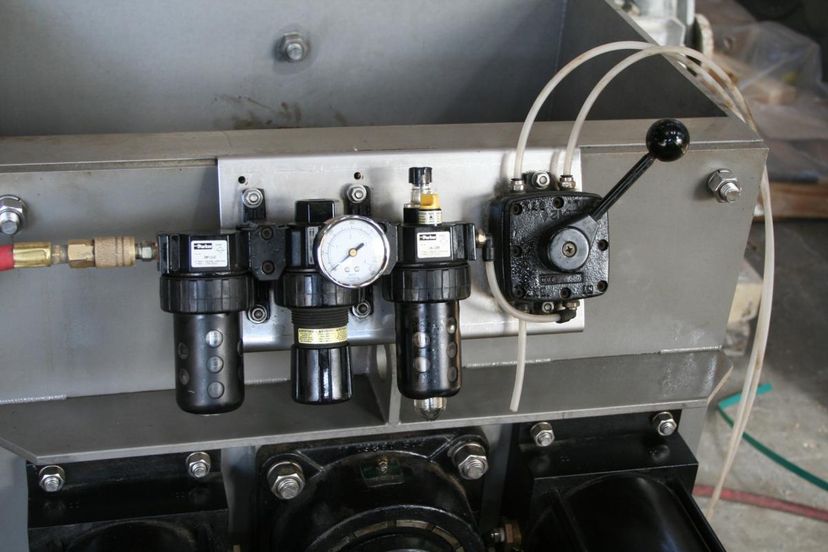
FRL SET WITH 4-WAY CONE POSITIONING VALVE
DISCHARGE CONE
The principal adjustment of the press is made with the dual discharge cone assembly. This component at the cake discharge end of the press acts as a door or stopper plug to restrict material from leaving the press. The more pressure exerted by the discharge cone, the drier the cake material will be leaving the press. Also, the motor amps can be expected to increase with added pressure, and throughput may decrease.
The discharge cone is moved in (actuated) by the air cylinders. Typical air cylinder pressures to actuate the discharge cone are in the range of 30 to 60 psi. Some materials will press only in a low range, say 10 to 20 psi. Other materials may press best with a pressure of 60 to 100 psi. Air consumption is minimal in all models, 1 to 2 cfm.
During initial, first-time, start up presses are generally started up with the discharge cone in the withdrawn position. This will avoid an unnecessary jam.
Note that with many materials it is necessary to start the press with the discharge cone in the closed position at low air pressure. Thin or soupy materials, like pumped manure or clarifier underflow, can tend to purge right through the press if the press is operated with the discharge cone open (in the withdrawn/”out” position).
However, with materials that are dry to begin with, such as sawdust or plastic wash tank sludge, it becomes more important to start with the discharge cone in the open position. This is because these materials may tend to jam or overload the press. Similarly, high freeness materials, from which the water falls away freely, will have a tendency to jam in a press. Be sure to start the press with the cone open, and gradually close it with low air pressure, when running such materials for the first time.
Once you are through the initial start up, it will be unlikely that your press should have the cone opened before starting. Most operators rarely open or shut the cone once it is set.
As the pressure on the discharge cone is increased, not only will the cake become drier, but the flow through the press may also be reduced. With very slippery or slimy feed material it may be possible to apply enough discharge cone pressure to stop the flow altogether.
High discharge cone pressures can result in increased quantities of suspended solids in the press liquor.
Care must be taken if a press is to be left running at a very low pressure like 10 psi. If some fiber enters between the cone bushings and the screw shaft, it will take more than that much air pressure to close a cone which has been pushed open by a heavy flow of cake. The result will be either high moisture content in the cake or, worse, purging.
With some feed materials, the press can be operated with the discharge cone in the withdrawn position. The screws alone may do enough compressing and dewatering to produce a cake at the discharge.
It is acceptable to open the discharge cone, in most cases, during normal operating conditions. This allows inspection, while in operation, of the discharge end of the screws and screens. This will give the operator a chance to observe operation with minimum dewatering and maximum throughput. It is also a good technique for purging bad material, i.e. either jammed or spoiled material, from the press. (Do not try this trick if you are pressing hot or chemically aggressive materials.)
Where very low air pressure is required for proper operation, it may be practical to put the cone positioning valve in the neutral position, half way between open and closed. A press can not be left permanently in this condition: keep in mind that a slug of cake will push the cone open, and it will not re-close on its own afterwards.
An unusual technique is to set the air pressure so that the cone normally stays completely shut. A timer is used to periodically open the cone. The closed period is determined by the amount to time required for press cake to accumulate in the press. This type of operation is used with slippery or slimy press cake that cannot be dewatered to sufficient firmness to force the cone to open. The duration of the “cone open” period is long enough to dump most of the press cake that has been formed. Cone Timer panels are available from Vincent at a minimal cost.
Once through start-up, the cone is almost always left in the closed position at whatever air pressure had been found to be effective. A plug of cake will be left around the cone whenever the press is turned off; this will clear on its own accord on restarting the press.
There are a few applications where the air cylinders are removed and replaced with a jacking bolt. This is used if the cone pushes completely closed even with the lowest air pressure. It results in operating the press with a fixed discharge annulus. Alternatively, air cylinders with linear actuators are available.
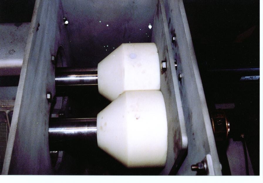 DISCHARGE CONE
INTERMITTENT OPERATION
In the case of intermittent operation, it is recommended that the control panel for the feed pump or conveyor which feeds the press should have a timer. This timer should be set to have the press run for two minutes after the feed pump (or conveyor) shuts off. This will partially clear the press so that it will not trip out on overload when it is re-started. (This applies in high torque applications or in installations where the material in the press dries out or freezes.)
Minimize the time that the screw press is run with no material being fed into it. The last material admitted to the press will dry to powder, and it can cause severe accelerated abrasive wear.
Initially the press will likely be run empty in order to check rotation. Even though some rubbing may be heard, negligible wear will occur so long as this period is kept to a minimum. Also, since the screw is supported to some extent by the material inside the press, running dry may allow the screw to rub the screen. (See the previous section, INVERTER VFD & PLC CONTROL.)
DOUBLE PRESSING
Some processes benefit from what is called double pressing. This means that the cake coming from the press is run through the press a second time (or through a second press). If little moisture is removed in the second (double) pressing, then it is known that the liquid removed in the first pressing is all of the free liquid that there is to be pressed out.
Sometimes water is added to the cake in between the first pressing and second pressing. This is done to enhance the recovery of dissolved sugars in the original press cake.
Molasses can be added to press cake between the first and second pressing. This is used to infuse dissolved sugar into the cake, increasing the solids content of the final press cake.
Capital-effective double pressing can be achieved by using an inexpensive Soft Squeeze Series KP screw press for the first pressing, following with a tighter-pressing Series TSP in the second position.
MOISTURE CONTENT
A screw press separates free water. This will leave organic water in the press cake. The organic water is either bound to, or part of, the animal or vegetable molecules. Mechanical pressure alone will not remove organic water; it takes heat or chemistry. Frictional heat from the press can remove organic water, but this obviously should be avoided. For chemistry, see the HYDRATED LIME, GYPSUM AND ALUM section. For heat, see the FLUID INJECTION section.
To determine the moisture content of a material (feed to the press, press cake, or press liquor), a sample should be weighed and dried overnight at a temperature slightly less than 100o C. (If sugars are present, use less than 70º C to prevent caramelizing.) The sample should weigh six or more times the tare weight of the sample tray or cup.
The moisture content of press cake varies considerably. Tomato press cake will be 90% moisture. Orange peel will be 80%, unless it is reacted with hydrated lime, in which case it will go down to 72% moisture; add molasses and it will go to 65%. Dairy and hog manure will come out at 70% moisture, unless there is sand or sawdust in the sample, which will reduce the moisture content. Cellulose fiber from a paper mill (knots, screen rejects, primary clarifier underflow) will come out about 50%. However, if secondary (biological) sludge is added, then the moisture content of the cake will go up considerably. With high ash content in paper mill samples, moisture may go down to 40%. Moisture contents of only 25% can be achieved pressing things like sand, eggshell, glass, and plastic chips.
The heat from steam injection can change the chemistry of the material being pressed so that cake with lower moisture content is produced. This blanching or parboiling effect works with fish and orange peel, for example.
A quick approximation of what to expect from a screw press is to squeeze as much water out with your fist, and figure that the press will do a little bit better. A better way is to twist a ball of the material in a cotton cloth.
COMPRESSION
A screw press achieves compression using several methods: (1) The discharge cone of the press causes back-pressure on the material being dewatered. The higher the cone pressure, the greater the liquid removal. (2) The pitch of the flights of the screw tightens as the material is conveyed through the press. This forces liquid to go through the screen. (3) The diameter of the shaft of the screw may be increased progressively, forcing material outward, against the screen. This is a tapered shaft design.
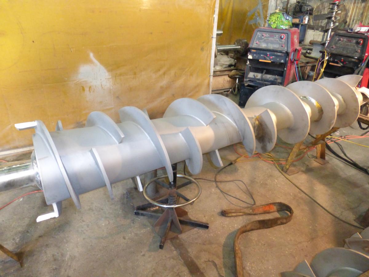
SCREW WITH TAPERED SHAFT
Force-feeding (supercharging) the press and applying a vacuum to the outside of the screen are two additional methods which may achieve compression. These two are used infrequently because the performance results are uncertain.
PRESS SPEED (RPM)
In general, the slower the screw speed, the greater the dewatering. Longer residence time in the screened area results from lower screw speed, which allows time for more thorough dewatering. Unfortunately, it also goes with reduced throughput capacity.
Screw press speed (rpm) can be changed by using a Variable Frequency Drive (VFD). Alternatively, the drive motor can be switched to a different pole motor (900, 1200, or 3600 versus the standard 1800 rpm). Most modern motors are good for permanent 120 Hertz operation; they are always good for a test at this high speed.
Higher speed can result in premature gearbox failure. Switching to synthetic oil, replacing the normal mineral oil, is recommended. Consult the factory for assistance.
The smaller Nord gearboxes are all rated for 4,000 rpm input, which makes it easy to switch to a 3000/3600 rpm motor. It is best to switch to synthetic lubricant if this change is permanent. With other gearboxes, the higher speed can result in premature gearbox failure. Consult the factory for assistance.
It has become normal for a VFD to be used with Vincent presses.
Low screw speeds are used for cooker crumb, potato peel, many sludges, and low freeness materials in general.
CAPACITY MEASUREMENT
The best way to measure capacity of a press is to collect timed samples of press cake and of press liquor. This should be done during a period of sustained, stable operation, rather than by timing a batch through the press.
Press cake is generally captured in a tarpaulin, and press liquor in a 5-gallon pail or 55-gallon drum. When the drain is at floor level, a 3-mil plastic bag can be used to catch press liquor. If the press liquor goes to a pit or tank, the change in depth can be timed.
Sometimes it is possible to collect only one flow, either press cake or press liquor. In these cases it is possible to estimate the press throughput if the solids content of the inbound material and press cake are measured. It is assumed that there are zero suspended solids in the press liquor, although this is never really the case.
A/B/C/D-PLATES
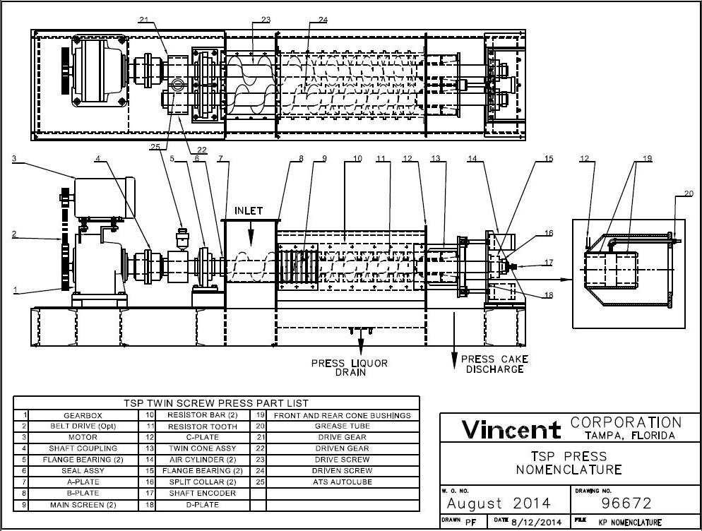
There are four vertical plates making up the frame of the press. These are called out in the Nomenclature drawing at the end of this manual.
Starting from the drive end of the press, the first one is the A-plate. This A-plate forms the wall of the inlet hopper closest to the gearbox. The shaft seal plates are bolted to the A-plate.
The next plate is the B-plate. It forms the downstream wall of the inlet hopper. The screen starts at the B-plate.
The third plate, the C-plate, supports the discharge end of the screens. The discharge cone touches this plate when the cone is in the closed position.
There is a fourth plate, called the D-plate, on which air cylinders and thrust bearing are mounted.
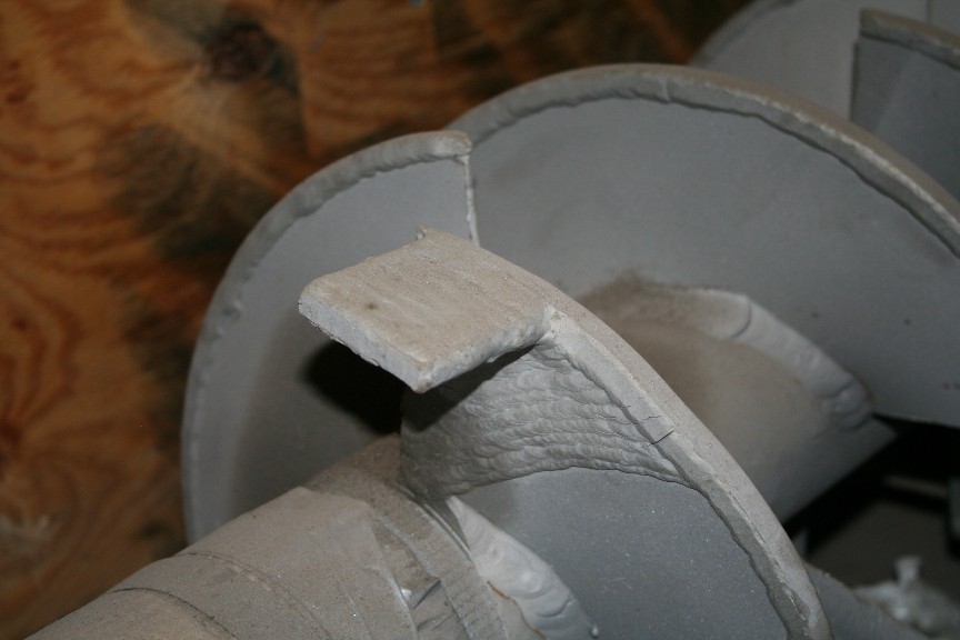
SCREW LIFE
If a press loses its previous throughput capacity, or if cake moisture content increases, it can be a sign of a worn screw.
A screw can last anywhere from six months to twenty years. It depends on the material being pressed and how hard it is being pressed.
Premature screw failure can arise from several causes. The two main ones are:
(a) If a press is allowed to run continuously even when no material is being fed into it, the screw can wear out in one or two months. The same can happen if a very low flow is consistently fed into the press.
(b) If abrasive material is dewatered with high cone air pressure, rapid wear will occur. This condition is avoided if a few drops of water can always be squeezed from a fistful of press cake.
Two effective ways to extend screw life are:
(a) Various grades of hardsurfacing rod can be used to protect the flights of a screw. The best hardsurfacing will have Tungsten Carbide impregnated in it.
(b) Using a VFD or lower speed motor to reduce the screw rpm will extend screw life.
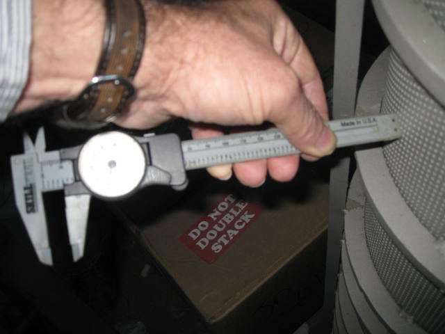
If a worn screw is suspected, the thing to do is to shut down the press, open the cone, and dig out the cake until the tips of the last two flights can be seen or felt. Check how badly the tips are worn. If the there is 3/8″ between the tips and the screen, serious wear is evident. It is also an indication that the sharp edges of the flights throughout the press may have worn, becoming rounded. This can cause the flights to act like a putty knife, plastering solids against the screen, preventing water from coming through.
Worn screws are either restored locally or returned to Vincent for rebuilding. The cost of a screw rebuild is around one third the cost of a new screw.
SCREW CONFIGURATION
All Vincent screw presses use the interrupted flight screw design. The interruptions leave room for stationary resistor teeth, mounted rigid to the frame of the machine, to reach almost to the shaft of the screw. This design of screw press stands in contrast to a continuous screw design. The advantage of the interrupted design is a reduced tendency for the material being pressed to co-rotate with the screw. Also, there is more agitation within the press and, consequently, quicker and more thorough dewatering.
The screw starts with a feeder section of continuous flights. This picks up material in the inlet hopper and pushes it into the screened part of the press. The feeder section ends at the first set of resistor teeth. The feeder section of the screw is followed by compression stages where the flights have reduced pitch. The reduction in pitch of the flights results in compression of the material going through the press. Twin screw presses are made with three to seven stages of compression.
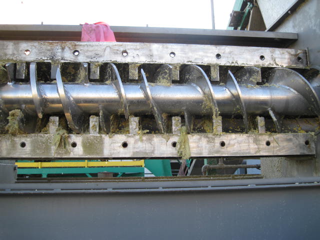
INTERUPTED FLIGHTS, RESISTOR BARS, and RESISTOR TEETH.
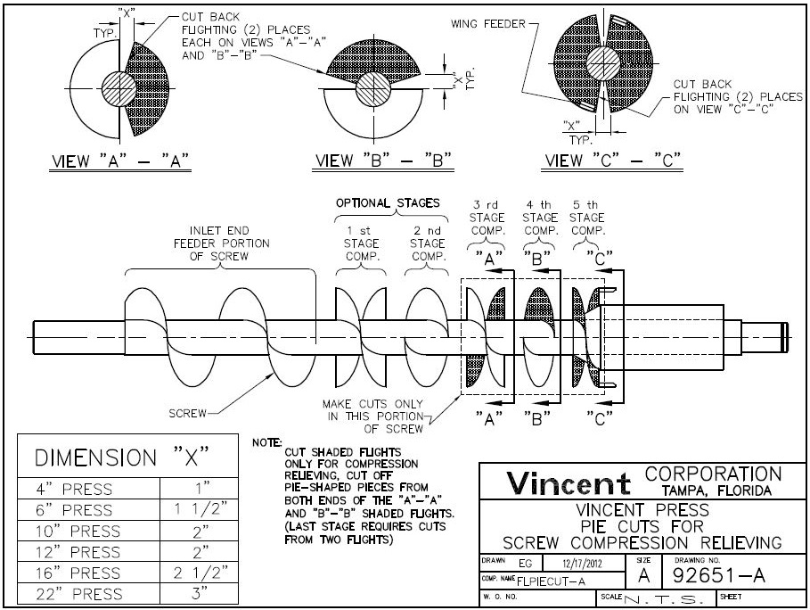
PIE CUTTING
Sometimes the compression of a screw is reduced, in the field, in an operation called “pie cutting”. This involves cutting pie-shaped segments from certain flights of the screw, leaving a butterfly (end view) configuration. The modification is done to avoid excessive compression and jamming. The “sterile cut” is more dramatic. Consult the factory for assistance before making this modification.
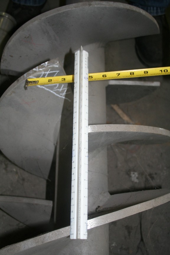
4″ PIE CUT PIE CUT
NOT PIE CUT BUTTERFLY CUT
JAMMING
Should a press trip out on overload because it has become jammed, a series of steps can be taken to un-jam the press. Generally, the easiest thing to do is to reverse the leads on the electric motor drive. This will cause the screw to feed material backward into the inlet hopper.
Generally jamming is caused by over-pressing excessively dry material. Running the press backwards will break up this material. If the jamming was caused by tramp material, hopefully this can be found and retrieved from the inlet hopper following operation in the reverse direction.
Having a VFD with a reversing button greatly facilitates this operation.
If a press has had extensive use in an abrasive application, the outer diameter of the flights will be worn away at the discharge of the press. Radial wear of 1″ to 4″ in larger presses will lead to serious jamming and, possibly, a burst screen.
When a press is operated in the reverse direction it is possible that solids in the press will be forced against the A-plate. This can damage the shaft seals. For this reason, care should be taken when running the press backwards.
Usually three or four revolutions of the screw are sufficient to clear a press. If running the press backwards several cycles does not clear the jam, a screen should be removed so that the cause of the jam can be determined. Look for a bent flight. Before going to the trouble of removing the screen, shut down the press, lock it out for safety, and try clearing the end of the press with a long screwdriver or pry bar.
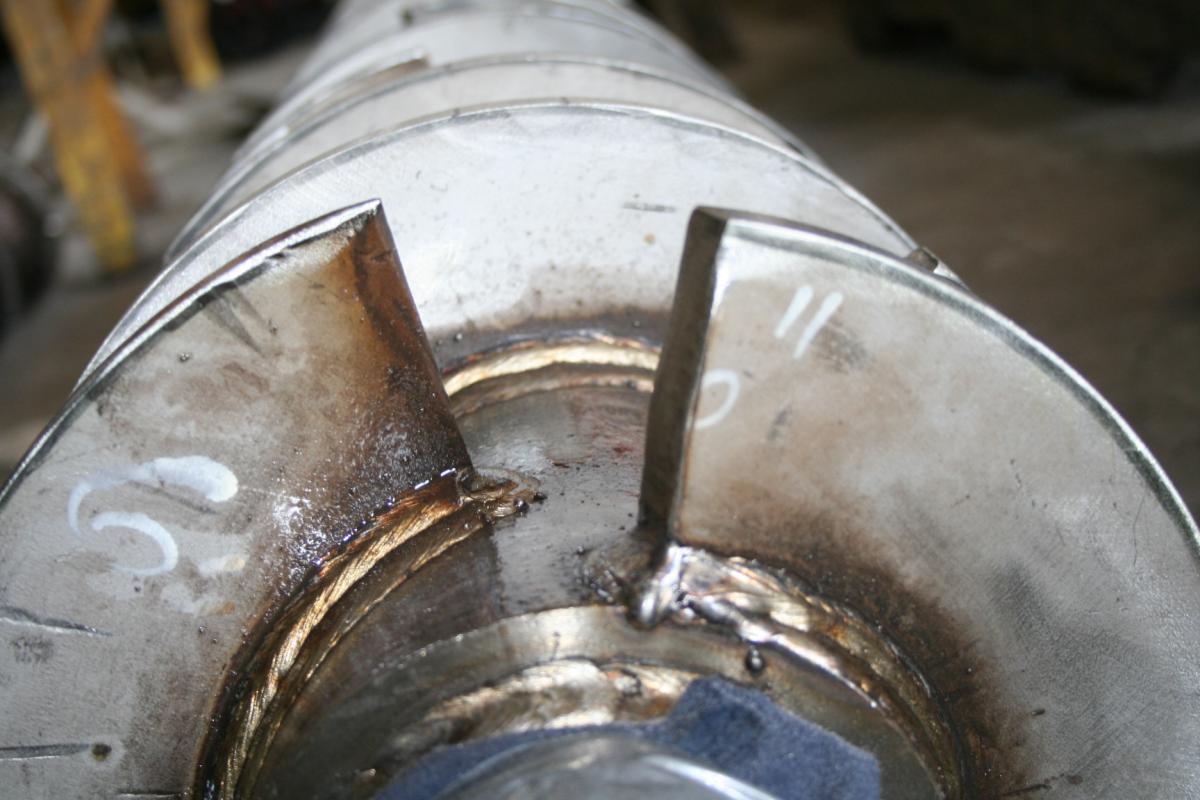
Sometimes when a press is jammed, a flight on the shaft of the screw will fold backwards, toward the gearbox. This can happen if tramp metal is caught between a flight and a resistor tooth. The weld at the shaft may tear. When this happens flow through the press is greatly impeded.
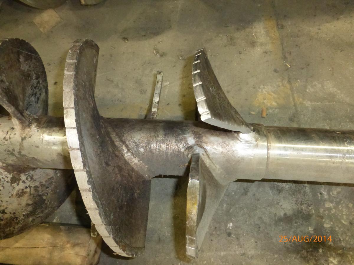
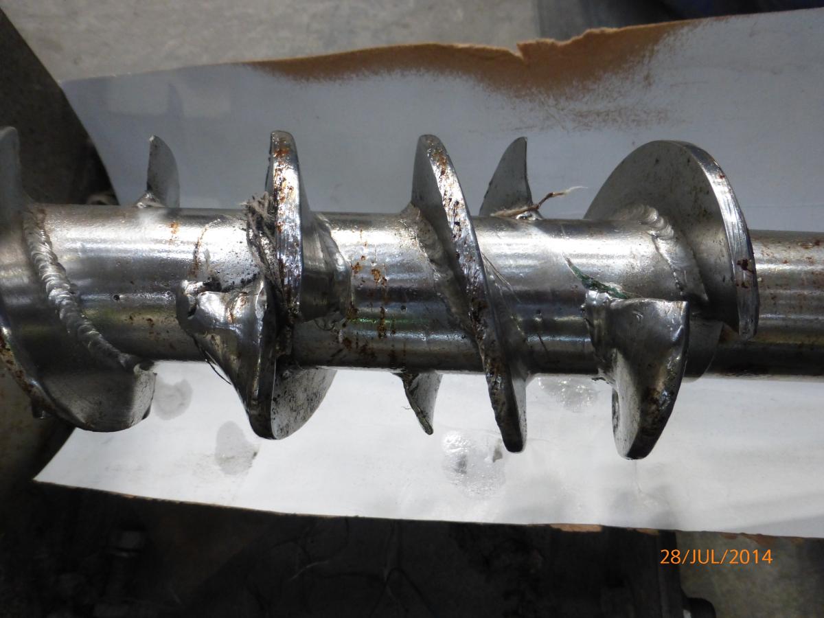
FOLDED FLIGHTS
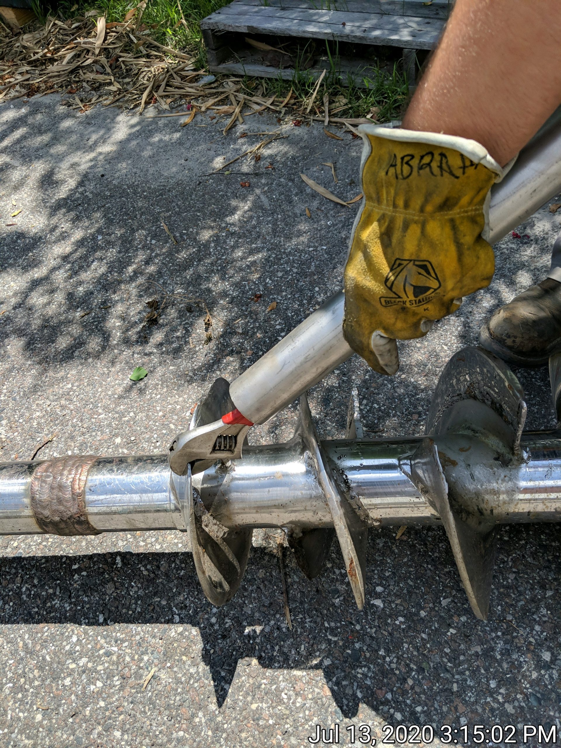
It may be possible to repair a damaged screw without taking it out of the gearbox. Flights which are not too severely bent can be bent back into position by gripping the flight with an adjustable wrench. Be sure to wear heavy leather gloves when doing this, because the wrench will have a strong tendency to slip loose. See the photo on the following page.
If you are straightening the flights with hammer blows, applying heat with an oxyacetylene torch can help.
If the end of a flight has been ripped off the shaft, breaking loose the weld, or if it is severely bent, just use an angle grinder to cut away the bad part. Similarly, bent resistor teeth can also be trimmed with a grinder so that they do not hit the flights.
SCREEN BLINDING
A common problem is for the screens of the press to become blinded (covered over). When this occurs, the flow of press liquor coming through the screens diminishes. The level in the inlet hopper will fill up to where it overflows.
In some cases, the screens can be cleared by periodically reversing the direction of rotation of the screw. This can be programmed with many VFDs, so that the press runs forward for a given period and then reverses direction briefly for three or four turns when the screens start to blind. This is one of the easiest possible solutions to test. Sometimes it is the only one that is effective. The technique works well on bar screens; care must be taken with perf screens so that the screw does not snag the screen during the reverse cycle.
Many other methods are used to address blinding: (1) Adding notches to the screws, (2) Reducing or eliminating the pressure in the inlet hopper, (3) Adding press aid to the flow, (4) Changing to a different screen selection, (5) Reducing the screw-to-screen clearance, and/or (6) Employing a screen flush with caustic solution, acid, or high pressure spray.
If blinding occurs after an extended period of satisfactory operation, it is usually due to wear of the screw. Rounded edges of the flights will contribute to blinding.
CHANNELING
A condition somewhat similar to purging can occur with slimy materials, like concord grapes, pineapple pulp, or spent brewer’s grain. These may tend to channel or squirt out from one side of the cone. Two ways to eliminate channeling are to lower the air pressure on the discharge cone and to slow down the speed of the screw. Channeling can also be reduced by adding press aid to the material being dewatered, or by reducing the inbound flow to the press.
To break up channeling, pieces called wing feeders can be welded to the end tips of the last two flights of the screw. See the WING FEEDERS section of this manual.
PURGING
An undesirable condition can occur when the material being admitted to the press purges, without liquid-solid separation, from the cake discharge. This can occur especially if pressure exists in the inlet hopper.
Mechanically, purging occurs when a dry lump of press cake holds open the discharge cone. Unpressed material will flow around this partial plug.
Purging may occur when there is a much reduced, small flow of cake coming from the press. Usually this is a sign of blinded (covered over) screens. This can be caused by a worn screw. Liquid from the inlet hopper will wick into the press cake, making it soft enough to blow out. Sometimes this condition is avoided by mounting the press inclined at about 5o above horizontal; the simplest way to do this is to place a block under the cake discharge end of the press.
Wing feeders are welded to the tips of the last two flights of the screw in order to break up dry cake which will hold the cone open. If you install your own, be sure that they do not hit the cone when it is closed.
A drop in operating amps can be an indicator that a purging condition has begun. An ammeter circuit can be installed to trip the system when a reduction in motor amps occurs. This is rarely done.
BRIDGING
Sometimes bridging will occur at the inlet hopper, preventing material from flowing into the press. The best way to prevent bridging is to control the feed rate going into the press so that the screws are never completely covered over. If an independent surge hopper is mounted over the inlet of the press, it should have at least one, preferably two or three, vertical walls. This will minimize bridging of the surge hopper.
Bonding Teflon sheets to the inlet hopper of the press is a remedy that has been used to reduce bridging of bulky materials which allow free-draining of water.
A vibrator, mounted on the side of a feed hopper, may also alleviate bridging.
One way to overcome this is to direct a stream of water into the inlet hopper to break the bridge. The nature of the screw press is that essentially all of this added liquid will be removed in the pressing operation. (It may be convenient to pump a jet of the press liquor into the inlet hopper to break the bridging.) This is rarely done.
RESISTOR TEETH
The interrupted screw design press has stationary teeth that protrude into the flow of material as it passes through the press. These fit into the gaps of the screw where there is no flighting. They stop just short of the shaft of the screw.
The resistor teeth are an integral part of the resistor bar. These resistor bars are positioned axially, parallel to the screw, with one bar above and one bar below each screw. The resistor bars are bolted between the B- and C-plates; they form a part of the structural frame of the screw press. The screen frames bolt onto the resistor bars.
Not infrequently the resistor teeth are drilled so that fluid can be injected into the press during operation. See the next section.
Sometimes resistor teeth are bent by tramp material so that they are hit by the screw flights. Grinding a little off such a tooth with an angle grinder can solve this problem.
Rarely the resistor teeth are shortened, usually by half, to increase the capacity of the press. Removing the teeth altogether will result in co-rotation and jamming.
FLUID INJECTION
Resistor teeth can be drilled to permit injection of steam, solvent or water while the press is in operation. Also, these modified resistor teeth can be used for partial CIP cleaning, without the need of removing the screens from the press.
Commonly alcohol injection is used to achieve in-line washing to remove sugars. Hot water injection is used to recover dissolved solids in juice production. Steam injection is used in dewatering raw organic materials.
The moisture reduction that results from steam injection is related to a chemical change that comes with blanching, or parboiling, a material. Steam injection works well on pineapple skin, citrus waste, and raw fish. Tests run with steam injection in a Vincent press at Anheuser-Busch showed little benefit. The material being pressed, spent grain, had already been “cooked” before steam was added.
Injection is achieved by drilling holes through the resistor teeth and piping these holes to a manifold outside of the screen. Photos and drawings are available from the factory. Vincent does not charge for providing a drilled resistor bar.
STEAM INJECTION LAB PRESS
IN TWIN SCREW PRESS STEAM INJECTION
POLYMER
In rare applications, the addition of polymer is indispensable in achieving adequate screw press performance. Polymers are added to dilute waste streams, especially to those containing very small size suspended solids. The long chain molecules of the polymer will flocculate the solids, agglomerating them to the point where they can be pressed. Under the right conditions, drastic improvement can be observed in press throughput, press cake moisture, and press liquor clarity.
Nalco and GE are the leading polymer suppliers. Their sales engineers are anxious to recommend the product best suited for your application.
Low speed operation of the press is usually required in order to achieve good performance.
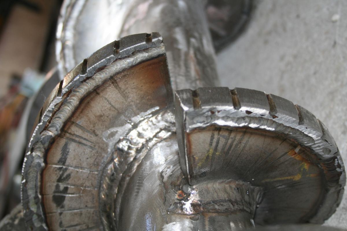
NOTCHES
Sometimes it is necessary, during press operation, to have the screw wipe the screens clear of blinding material. This is best achieved by having notches in the outer edge of the screw. Fibrous material accumulates in the notches and brushes away slimy material which may be blinding the screens. Shallow notches (1/8″ wide by 1/8″ deep, 1-1/2″ apart) in the outer edge of the screw flights work well. Typically, notching is done from the B-plate to the second resistor tooth. Most Vincent presses are supplied with notches.
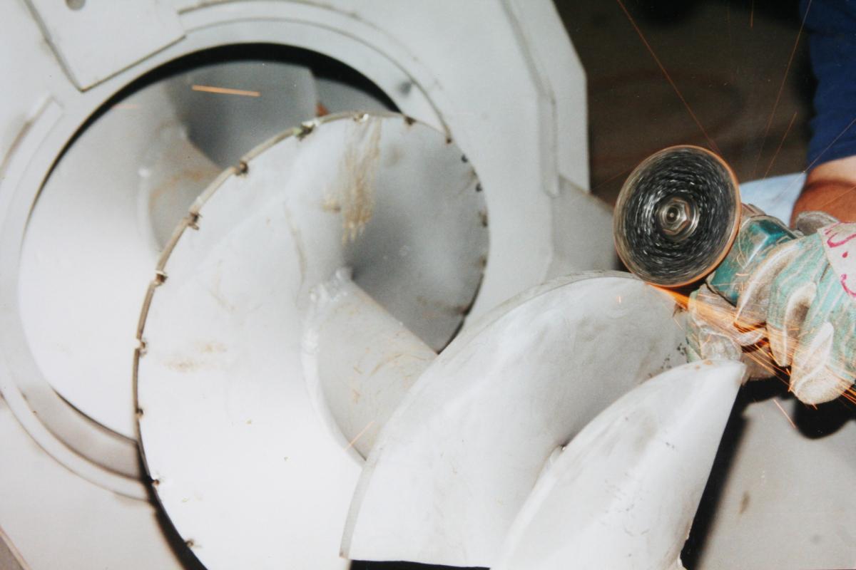
GRINDING NOTCHES IN THE FLIGHTS
WIPERS
Before the advent of notches, wipers, made of UHMW strips or nylon brushes, were (rarely) mounted to the outer perimeter of the screw flights. If at all possible we advise against the use of such wipers because (a) they tend to cause material to co-rotate and jam in the press, (b) they are difficult to replace, and (c) they wear rapidly, resulting in unacceptably frequent shutdowns for replacement. Wipers tend to improve dewatering performance for the first week or so. After that the wiper material wears and press performance reverts to being just a little better than if no wipers were used. Wipers are made either of 1/4″ thick high durometer polyurethane or of nylon bristle brush. Wipers are preferably mounted on the downstream edge of the flight.
PRESS AID
Some materials press best if a press aid is mixed into the material to be pressed. Typical press aids are rice hulls, cottonseed hulls, cellulose fiber from a paper mill, and ground newspaper. Ground wood is the best, but most expensive, press aid.
Press aids are most commonly used in producing juice from deciduous fruit. The press aid gives the press something to get a bite on. Press aids also tend to hold back fines (short fibers) and prevent them from going through the screens with the press liquor. If apples are fed into a press, apple sauce will come through the screens. However, if a press aid is added to the apples, then apple juice will come through the screens.
Typically, the amount of press aid used is only 1% to 3% by weight of the flow going through the press. This will look like more than such a small percentage because press aids have a much lower bulk density than the wet materials that are pressed.
HYDRATED LIME, GYPSUM, AND ALUM
Lime (calcium hydroxide) must be added to citrus peel before it can be pressed. The lime breaks down the pectin or cell walls so that the press can remove moisture. Less than 1% by weight is used. A reaction time of several minutes must be allowed prior to pressing. Lime has been used successfully in the same manner with potato, onion, tomato, carrot, and pineapple waste. It works well on acidic materials such as strawberries and coffee bean pulp. Vincent offers lime dosing equipment.
Gypsum and alum salts are also effective chemical press aids. They are typically used in dewatering sugar beet pulp, and they have rarely been found effective on other materials.
VACUUM EFFECT
In some applications, increased screw press capacity can be obtained if the area outside of the screens is under a vacuum. This can be achieved by mounting the press at a high elevation, with the press liquor drain line dropping below the surface of a drain tank or pit.
That is, the drain line from the press should go below the surface of the pit or pond into which it drains. If this line is relatively small in diameter and has a steady downward slope, a vacuum will be induced around the screens of the screw press. The mass and velocity of press liquor flowing through the drain line create this vacuum. To draw air bubbles downwards with the press liquor, the velocity of the fluid must be greater than five feet per second.
The covers over the screens of the press will have to be sealed, usually with Silicone.
The amount of vacuum is a function of the elevation between the press and the drain pond. For good results, the press should be mounted on a stand that is 20′ tall or higher.
PRESS LIQUOR
A screw press produces relatively “dirty” press liquor as compared to a filter press or belt press. Suspended solids will pass through the screens of the screw press along with the liquid being expressed from the inbound material.
If suspended solids need to be removed from the press liquor, the most common method is to pump the press liquor either over a static (sidehill) screen or through a rotary drum screen. Generally, the screen tailings (sludge solids) are fed back into the screw press along with the flow of inbound material. Most of these fines will be captured with the solids of the inbound material and end up in the press cake. Although some of these tailings will once again go through the press screen with the press liquor, equilibrium of recirculating solids is reached and satisfactory pressing operation is realized.
If the press liquor is to be concentrated in an evaporator, better screening than can be achieved with a static screen may be required. Another Vincent machine, the Fiber Filter, provides premium performance. Decanters or centrifuges may be required.
SCREEN SELECTION
The screens of the press are made either of wedgewire (slotted screen) or perforated stainless sheet (round holes). Wedgewire screens are expensive one-piece weldments that must be replaced when excessive damage or wear has occurred.
Wedgewire screens in Vincent presses can be reversed in order to achieve double life. That is, wear starts at the cake discharge end of the press. When this occurs, the screen can be turned 180o so that the fresh inlet section is then located in the discharge area.
Screens made of wedgewire come standard with 0.015″ to 0.020″ slot width; they are also available with slots that are 0.008″ to 0.060″ wide. With slot widths less than 0.012″ there is a tendency for the screen to blind (be covered over) with the material being pressed. However they work well in alcohol and oil separation. Changing the slot width generally has little impact on the clarity of the press liquor or the dewatering capacity of the press.
The most common damage to a wedgewire screen is for part of the surface to be smeared over by rubbing the screw. This rarely is bad enough to affect press performance. Profile bar screens generally work satisfactorily with 30% or even more of their surface smeared over.
Smeared screens can be remedied by cutting open the slots with a die grinder with a very narrow disc.
TIG welding is used to close the gaps in the case where either a few wedgewire slots get spread apart by tramp material or a perforated screen gets torn.
Perforated metal screens are simple sleeves which are held in the screen assembly. These are less durable but inexpensive to replace. Standard perforated screens have a hole size of 3/32″ diameter, although material with 0.050″, 0.033″, down to 0.023″ holes can be supplied.
Frequently, increased press capacity can be achieved by changing a perforated screen to one with smaller holes. This unexpected result arises from a combination of factors: (1) smaller hole screens are made of thinner sheet metal, so that the press liquor has a shorter distance to travel before it falls free from the screen, reducing the chance of sponging backwards through the screen and (2) particles which fall into and plug a larger hole will roll over a smaller hole.
Minor rubbing between the screw and screen is normal, although, obviously, hard rubbing will cause wear and premature failure of the screen. With a clearance greater than 3/16″, the dewatering performance of the press can start to deteriorate; this depends a lot on the nature of the material being dewatered.
In cases of severe wear or damage, it is common to patch a screen. Stainless sheet metal is used for this. The reduction in drainage surface is of little consequence as the screens have ample open area.
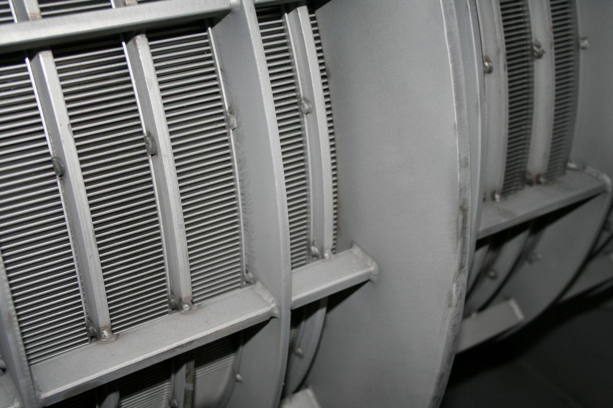
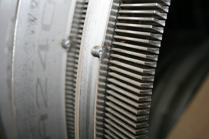
PROFILE BAR (WEDGEWIRE) SCREEN
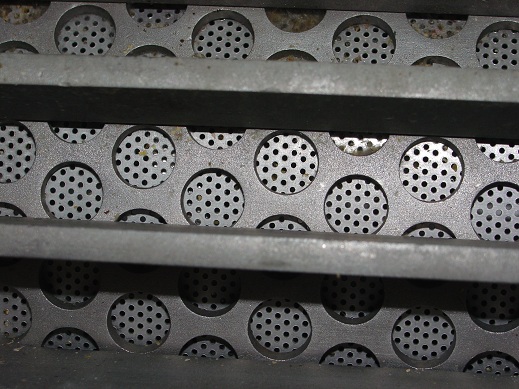
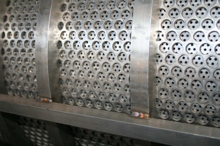
PERFORATED SCREEN WITH REINFORING SHEET
SCREW-TO-SCREEN CLEARANCE
Generally the clearance between the screw and the screen is 1/16″, plus or minus 1/16″. The screw should not rub the screen hard, as it can cause wear and premature failure of the screen. Tight clearance is used with materials that blind the screen, such as onion skins. Greater clearance is used with eggshells, pectin, xanthan gum, and corn husk, for example. With a clearance greater than 3/16″, the dewatering performance of the press can start to deteriorate; this depends a lot on the type of material being dewatered.
To measure the screw to screen clearance in wedgewire screens, a feeler gauge can be slipped through and along a slot until it hits the edge of the screw. Measure from the outside of the screen to the edge of the flight; then subtract the thickness of the wedgewire (generally either 0.375″ or 0.500″) from the measured depth in order to calculate the clearance.
Alternatively the screw-to-screen clearance can be checked by removing one half of the screen. Inspection is made from the side from which the screen half has been removed.
In the case of perforated screen installations, a depth gauge can be used to measure the screw-to-screen clearance. This is done by first finding an area where the screw flight is next to the screen; poking a straightened paper clip through the screen is handy for this purpose. The depth from the outside of the screen to the edge of the flight is measured, and then the thickness of the screen is subtracted from that measurement. [3/32″ perf is 0.075″ thick; 0.050″ perf is 0.048 thick; 1/32″ perf is 0.024″ thick; 0.023″ perf is 0.018″ thick; 3/8″ perf back up screen is 0.120″ thick.]
If a screw rubs against the screen in a given area, it may be best to grind some off the OD of the screw. Prussian Blue can be useful in finding the spot that is rubbing.
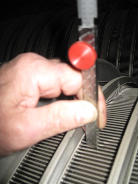
WEDGEWIRE DEPTH GAGE and PERFORATED DEPTH GAGE
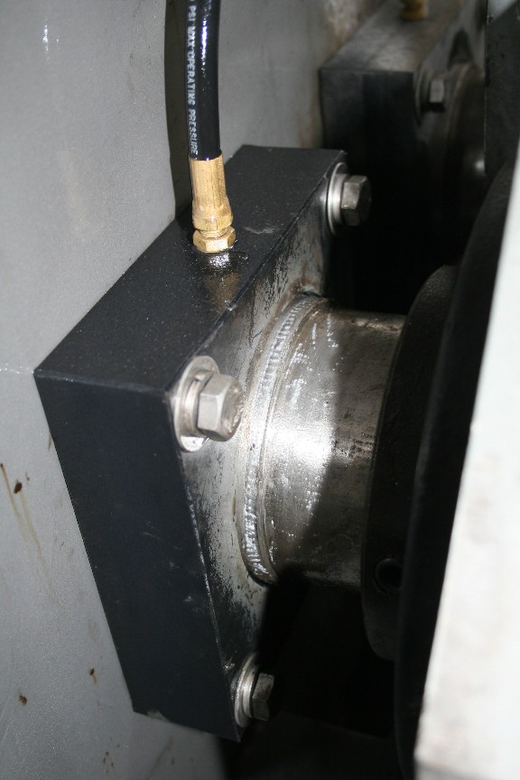
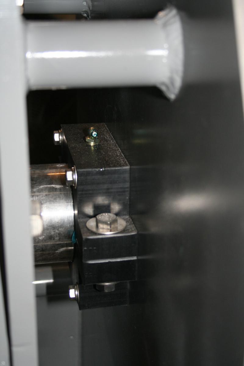
CONE BUSHINGS
The cone rides on the shaft of the screw. “Cone Sleeve” is the name given to the portion of the screw on which the cone rides. There will be either one or two bushings in each cone to support and guide it, and to protect the Cone Sleeve journal surface of each screw shaft. Sometimes these bushings are lubricated with liquid from the material being pressed, such as the juice from apples or water from pectin peel.
A grease fitting is provided for lubricating the bushings or to minimize leakage of press liquor through the cone. If there is only one grease line per screw, the grease line goes to a pocket, which serves as a grease reservoir, located between the two bushings. Bushing lubrication is extremely important when materials that are dry (like paper mill screen rejects) are being pressed. By the time such materials reach the discharge of the press, they do not have enough free moisture left in them to adequately lubricate the cone bushings.
Rarely, presses are supplied with additional lubrication fittings so that water, in addition to grease, can be metered to the bushings as a lubricant.
Automatic grease systems are available. These should be the high pressure (900 psi) electric or battery variety. Vincent provides these for critical applications, especially pulp & paper.
Liquid leaking past the cone bushings drains out the back of the cone (at the air cylinder end of the press). Almost always it is minimal compared to the flow of press cake. However, a pan can be provided to collect this liquid and drain it into the main flow of press liquor.
In many applications the cone is relatively stationary during press operation. For these it is recommended that the cone be opened and closed once a shift. Unless safety will not allow, this can be done with the press in operation. This smears grease over the cone sleeve of the screw shaft.
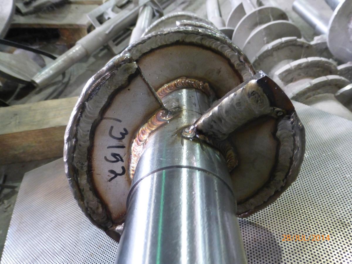
WING FEEDERS
There are blades welded to the outside tips of the last two flights of the screw. Called “Wing Feeders”, these are mounted parallel to the discharge screen surface. Care must be taken that wing feeders are not made so long that they hit the face of the cone when the cone is in the closed position.
Wing feeders are used in twin screw presses to break up press cake which tends to accumulate between the two cones. Material jammed between the cones will hold the cone open, resulting in wet press cake.
LONG WING FEEDER
CLEANING
Commonly, material is cleared from a press by stopping the inbound flow, setting the discharge cone in the withdrawn position, and running the press for a few minutes until no further material is discharged. This will leave some material inside the press, which can be handy for forming a plug at the cake discharge when the press is restarted.
Material will leave a Vincent interrupted flight press only if there is additional inbound material forcing it out. This makes it difficult to clear all material from inside a press without removing the screen. One technique used successfully is to feed crushed ice into the press. Water must be fed along with the ice to prevent jamming. When the ice melts, the press will be relatively clean inside.
There are applications in which the press must be cleaned frequently, such as once a shift, in order to meet sanitary regulations. The screen halves can be hinged to facilitate this. In other cases, the screens are removed from the press. A spare screen assembly may be kept, submerged in cleaning solution, in order to minimize the downtime required.
Cleaning the inside of the screen can be achieved, at least to some extent, by injecting water through the resistor teeth. Holes must be drilled in the resistor teeth to make this possible.
It is unusual that the outside of the screen needs to be cleaned. Spray systems for this can be built into the press at the Vincent factory. Alternatively, a pressure washer or swabbing with acid or caustic solution can be used.
SHAFT SEAL
The seal plate is bolted to the A-plate. This may be solid UHMW (ultra high molecular weight polypropylene or polyethylene) or it may contain one or two Johns Manville (JM Clipper) lip shaft seals. There may be a grease fitting on this plate; the grease is used to reduce leakage and to help prevent fiber material from entering and damaging the screw shaft.
Generally, seals are allowed to drip once they start leaking. They are replaced only in conjunction with major maintenance, as when the screw is removed from the press.
In some cases we have found that leakage from a shaft seal can be stopped by simply selectively loosening or tightening the four bolts holding the seal housing to the A-plate.
SEAL PLATE SPLIT SEAL PLATE
SCREW REMOVAL
The screws, as a pair, are removed through the hole in the C-plate, at the cake discharge end of the press. Vincent provides an anchor shaped clamping tool to hold the two screws together as they are removed from the press. The operation can be difficult the first time, so we recommend consulting with the factory before getting started. The press must first be de-energized and locked out prior to starting this procedure.
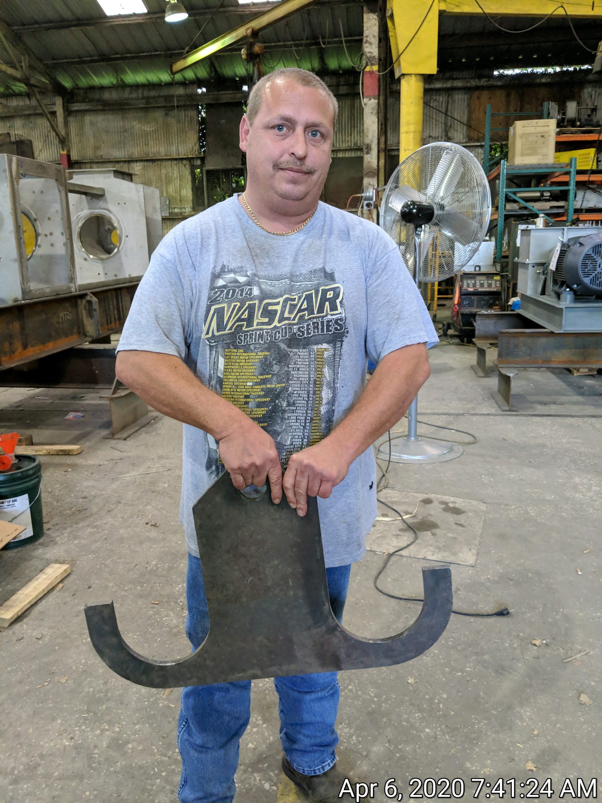 ANCHOR TOOL FOR SCREW REMOVAL
Start by removing the bolts holding the shaft seal plates to the A-plate. This will prevent damage once the screws are loose.
Remove any shaft encoders from the discharge ends of the screws. Also disconnect any sensors, grease lines, and pneumatic supply lines.
The bars with the resistor teeth must be removed before the screws can be removed.
To remove the screws from a Series TSP press, the shaft couplings between the gearbox and the screws must be undone. Then the gearbox must be moved out of the way so that the shaft couplings can be pulled from the ends of the screws. Falk gear-type couplings should be heated to 350º to 500º F so that they can be pulled off; use a temperature stick to measure this temperature.
Next the pillow block bearings are removed.
A hydraulic jack is used to pull the coupling halfs and the PB bearings from the shaft.
If a flange (thrust) bearing is mounted on a plate which also holds the air cylinders, do not remove the flange bearing by itself. Instead, leave it on the plate and remove the air cylinders and bearings as a single unit.
If the coupling half, pillow block bearing, or flange bearing have become seized to the screw shaft, it will be necessary to cut them loose. It is recommended to have spares on hand before removing screws from a press.
SCREW REPLACEMENT
In the case of the Series TSP presses, jacking bolts and shims are used to achieve proper alignment. Only after the screws are aligned within the screens can the gearbox be aligned to the screws (not the other way around). When working with gear-type couplings, be sure to leave the prescribed 7/16″ gap between the gearbox shaft and the screw shaft. This will protect the gearbox from thrust loads.
Falk gear couplings must be heated to 350º to 500º F in order to slip onto the shaft.
It is important to hand-pack grease into a Falk coupling. Do not rely on the grease fitting because the grease will only lubricate in the path of least resistance.
There are two ways to avoid excessive rubbing between a new screw and the screen: Either shims can be placed between the screen frames and the resistor bars, or the interference can be ground off the edge of the screw. To eliminate the high spots, coat the edge of the screw with Prussian Blue, bolt the screens in place, turn the screw, remove the screens, and grind the screw where interference is seen to have occurred.
SCREEN REPLACEMENT
Wedgewire screens are replaced as assemblies. There are no replaceable wear parts of wedgewire screens. The old screens are simply unbolted from the resistor bars and removed from the sides of the press. Installation of new screens is as simple as bolting them in place.
Wedgewire screens may become smeared from being wiped by the screw or by hard press cake. Wedgewire screens generally work satisfactorily with 30% or even more of their surface smeared over. Usually press liquor will come through a smeared area of a wedgewire screen. If it becomes an issue, it is corrected by running a die grinder blade through the slots.
In the case of screen failure, frequently a solid patch can be welded onto the screen, from the outside. This is simple as the screen need not be removed from the press.
The following covers only presses with perforated metal screens. Like wedgewire screens, these screens are held in frames that are split vertically, being bolted to the resistor bars.
Usually the perforated inner screens (screen inserts) are tack welded in place. However, if they bolt in place, once the new screen is tight against the frame, look through the screen and locate the holes in the frame where the attachment bolts go. Use a center punch to open holes in the screen insert. These holes must be large enough to allow the attachment bolts to go through the screen and thread into nuts on the far side of the frame.
Once the new screen is tack welded or bolted tightly in place, beat over and grind off the excess screen material.
There are two ways to avoid excessive rubbing between a new screen and the screw: Either shims can be placed between the screen frames and the resistor bars, or the interference can be ground off the edge of the screw. To eliminate the high spots, coat the edge of the screw with Prussian Blue, bolt the screens in place, turn the screw, remove the screens, and grind the screw where interference has occurred.
The most common cause of screen failure ties to failure of an outboard support bearing. If the bearing holding the end of the screw wears out, it can let the screw move enough to rub against the screen. As is the case with wedgewire screens, frequently a solid patch can be welded onto the screen, from the outside. This is simple as the screen need not be removed from the press.
GEARBOX BASICS
The Series TSP presses use foot-mounted gearboxes. Parallel shaft reducers are used in the larger models.
Gearboxes are rated, and sold, by their torque rating. The manufacturers generally offer their designs in progressively larger sized castings, or boxes. The larger the box, the larger the torque rating. Each box size will be available with different gear ratios. In order to keep the torque fairly constant, larger horsepower motors are used with the high speed boxes. Similarly, reduced horsepower motors must be used when a low output speed is selected.
Screw presses are designed around the size of the gearbox that is selected.
PRESS LUBRICATION
Lubrication is something we generally review with customer personnel during start-up. It is pretty straight forward:
CONE BUSHINGS: Once a shift
BEARINGS: Weekly
BUSHINGS: Weekly
SHAFT SEAL: Weekly
GEARBOX: Annually
AIR REGULATOR: Whenever empty (if a lubricator is being used)
GEAR COUPLING: Whenever opened pack by hand, covering all teeth.
MOTORS: Never
The most critical lubrication item has to do with the cone bushings. Before starting up a new press, the cone should be run in and out a few times to spread the grease around.
Lubrication of the cone bushings depends a lot on what is being pressed. With orange peel, there is enough press liquor juice acting as a lubricant that the bushings are lubricated only at the end of the processing season (to keep them from locking up on dried-out peel juice). The other extreme is at a paper mill where boiler fuel is made out of reject fiber. There is no free water left in the press cake, so everything is very hot and dry. We automatically supply a 900 psi ATS autolube on paper mill jobs. Another tough application is with vapor tight presses where there is apt to be solvent getting into the cone bushings. The solvent can dissolve and wash out the grease, so we like to see frequent lubrication of the cone bushings. (Food grade grease is used in this application since food ingredients are being produced by the press.)
If Vincent supplies an autolube for the cone bushings, it will be either battery powered or require a hard wired power supply. This should be actuated when the press is first placed in service. It should be set to give one small shot of grease every couple hours. We provide autolubes with large grease reservoirs, so they will go at least two weeks at the maximum greasing schedule. Once operations are stabilized, it may be practical to reset the timer dip switches so that it gets one shot every shift or once a day.
In any case, we tell the operators to run the cone open and closed once a shift because this will spread the grease. This is done with the press in operation.
If Vincent does not provide an autolube for a critical operation, we generally tell the operators to manually grease the cone bushings once a shift. We also tell them to run the cone in and out when they do the greasing, in order to spread the grease around.
The bearings and/or bushings holding the screw get greased on the customer’s normal schedule for that type of bearing, maybe once a week, or once a day, or once a month. Whatever grease the customer normally uses will be fine.
The shaft seal housing may have a grease fitting. This grease is to prevent fiber from getting into the seal. The seal should be given a shot of grease whenever the screw support bearings or bushings are greased.
The gearbox oil should be changed once a year. Use mineral oil for a normal 1800/1500 rpm input. Use the same grade oil, but synthetic, for input speeds of 2,400 rpm or more. (Sumitomo Cyclo’s, parallel shaft gearboxes, and Brevini and Bonfiglioli planetaries, are exceptions to this. The OEM manuals from these suppliers detail lubrication requirements.)
Some Nord gearboxes have an autolube canister located in the motor adaptor portion of the gearbox. It is located under a cast iron cap. This autolube should be actuated when the press is placed in service. Nord recommends replacing this autolube once a year.
The air regulator used with the discharge cone air cylinders may have a lubricant jar. If so, Vincent includes a can of light oil along with the air regulator which comes with our screw presses. The jar should be filled when placing the press in service and when the jar is empty, about once a year. It takes very light (sewing machine) oil. The oil helps prevent corrosion inside the air cylinders. (Most air cylinder manufacturers no longer recommend the use of lubricators.)
If there is a Falk gear-type shaft coupling, Vincent packs these with lubricant grease prior to shipment from the factory. The grease is re-packed only if the coupling is opened (which is rare). Packing must be done by hand so that all the gear teeth have grease.
We have never seen nor heard of anyone greasing the motor bearings.
REPLACEMENT PARTS
Most replacement parts are standard OEM components that can be purchased from their original manufacturer. The specification of these items is included in the parts list that follows. Only shaft seals and possibly bearings are apt to require replacement.
The most common wear parts in the Vincent Press are the screens, the screws, and discharge cone bushings. Vincent stocks some screens. Screws and cones are generally rebuilt at the Vincent factory. Be sure to specify the serial number of your press when ordering replacement parts or repairs.
A spare set of spur drive gears is recommended for TSP presses which use them.
SAFETY
This manual has left unstated the obvious safety hazard: A screw press, like any screw conveyor, is totally unforgiving. If clothing or a limb gets caught in a rotating screw, the screw will not stop.
Observe the following safety precautions:
• Wear safety glasses around the press.
• Avoid loose-fitting jewelry or clothing, including high-visibility safety vests. If vests are required, the Velcro, tear-away type are recommended.
• Always lock out electric and compressed air before working on the press.
• Dewatering presses squirt liquid out, particularly if screen covers are removed. If material is hot, acidic, or caustic, do not remove screen covers while operating.
• Wear gloves when performing maintenance.
• When removing the cone discharge mechanism, watch for pinch points. Be careful when removing or installing the screw and screen when they are fed through the C-plate as this is a particular pinch point.
• Never stand near a press being suspended during installation.
• Provide an E-stop button near the press.
• Keep hands out of the press inlet and press cake discharge area.
Click the link below for a pdf version of this page.